Oops! Something went wrong while submitting the form.
By clicking "Accept", you agree to the storing of cookies on your device to enhance site navigation, analyze site usage, and assist in our marketing efforts. View our Privacy Policy for more information.
Scaling High-Speed Assembly for a 4-Piece Whipped Cream Nozzle
Food & Beverage
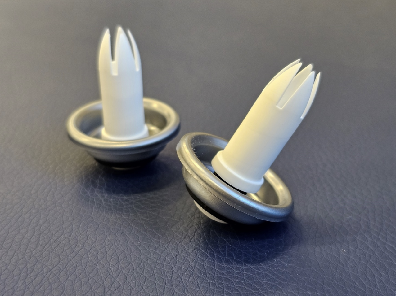
A food and beverage packaging manufacturer needed to bring a new 4-piece whipped cream nozzle assembly — cup, grommet, stem, and actuator — to high-volume production at 380 PPM with contractual performance targets of OEE ≥85%, scrap ≤0.5%, and reject ≤2%. The grommet’s molded geometry created specific assembly risks that had to be engineered around before any of those numbers were achievable.
Customer Background
In food and beverage packaging, valve and nozzle assemblies for pressurized food products carry a tighter quality floor than most consumer packaging. A whipped cream nozzle that fails to seal, vents inconsistently, or dispenses with incorrect flow creates both a consumer experience problem and a food safety exposure downstream.
This customer had internal equipment-building experience, but continuous motion assembly at 380 PPM on a multi-component molded assembly is a different engineering problem, requiring expertise in high-speed assembly. The 4-piece whipped cream nozzle was a new assembly for the customer, created to support demand from a new end customer, meaning production volume targets were contractual, not aspirational, and the machine had to be designed to specific OEE, scrap, and reject thresholds from day one.
The Challenge
The assembly consisted of four components — cup, grommet, stem, and actuator — each requiring controlled feeding, orientation, and sequential force-controlled assembly in a continuous motion environment at 380 PPM. The grommet introduced the most significant engineering risk, with three distinct failure modes that had to be designed around before the machine could reliably hit its performance targets.
Grommet failure mode 1: trapped flap. When the grommet was assembled to the cup, a thin molded flap near the retention feature could fold inward and become trapped inside the cup’s inner diameter. Functionally, this did not appear to affect seal performance but created an inspection problem that was effectively unsolvable by probing. If the condition was later determined to be a quality concern, the process would need to mechanically stretch or flex the grommet to pull the flap free, a motion that had to be designed into the machine before production began.
Grommet failure mode 2: incomplete snap. During stem-to-grommet assembly, the grommet could push upward under load rather than seating fully, leaving small sections of the grommet unsnapped beneath the stem’s retention feature. Like the trapped flap, this did not appear to affect function, it was a condition that could not be reliably inspected after the fact. The machine design needed to address it through assembly process control: specifically, a counter-punch approach that applied opposing force to hold the grommet in position while the stem was driven home.
Grommet failure mode 3: elevated assembly force and part damage risk. Assembling the stem into the grommet after the grommet was already seated in the cup compounded the force required; the grommet had less freedom to deform and distribute load. Without a controlled punch geometry that stabilized the sub-assembly during this step, there was meaningful risk of grommet damage or cup distortion at production speed.
Additionally, the grommet material was stiffer than typical gasket-style components — which affected feeding strategy, approach angle, and the force signature during snap assembly. A softer grommet self-locates more forgivingly; this one required the machine to do that work.
Why molded grommet geometry drives machine architecture decisions: Molded elastomeric components do not behave like rigid parts under assembly force — they deform, shift, and recover unpredictably depending on material durometer, feature geometry, and the sequence in which mating components are applied. At 380 PPM, there is no time for the grommet to self-correct between stations. The punch geometry, approach angle, force magnitude, and assembly sequence all need to be designed to produce a consistent grommet state on every cycle. When the grommet geometry also creates inspection-resistant failure modes, the machine cannot rely on downstream detection — it must prevent the condition from occurring.
The Haumiller Solution
Haumiller designed a continuous motion assembly machine to address all three grommet failure modes within the assembly sequence itself — eliminating the need for downstream inspection to catch conditions the machine was designed to prevent.
All four components were fed via UTI feeder bowls. The UTI platform was selected for its ability to handle the range of part geometries, from the rigid cup to the more compliant grommet, with the controlled orientation and feed rate required for continuous motion assembly at 380 PPM.
The cup was fed through an air track and picked up tangent around its smaller diameter on a rotating race, an approach that maintains cup orientation without requiring a mechanical grip. The grommet, fed hanging in a vibratory/air track, was introduced straight-in; because the grommet material was stiffer than a typical elastomeric gasket, a straight-in approach was viable without the grommet collapsing or misfiring at the entry point.
The stem was fed hanging in an air track and picked up above the grommet on a curve to control its tail orientation into the dial, then transferred to a stationary race. Tail control at this transition point was critical. A mis-oriented stem entering the assembly station would either jam or produce an incomplete snap condition.
To assemble the cup, grommet, and stem, Haumiller designed a lower single punch process. The lower punch traveled up through the cup and through the grommet to contact the bottom of the stem, then lifted against a fixed upper punch. The lower punch was cupped in profile to stabilize the sub-assembly during force application and prevent the grommet from displacing laterally as the stem was driven home. This geometry directly addressed failure modes 2 and 3: it resisted grommet upward migration under load and controlled the force distribution to reduce damage risk.
As the stem race ended and the grommet slide retracted, the punches began moved down to complete the three-part sub-assembly in a single controlled stroke.
The actuator was then fed hanging in an air track and picked up with zero-radius control, necessary for assembly at this speed to prevent the actuator from swinging out of position during transfer.The actuator was held by its flange resting on the pocket, while the cup sub-assembly was transferred above it. A punch then drove the actuator through the rotating cup sub-assembly, completing the four-piece nozzle.
Engineering Around Assembly Force and Part Control
The three grommet failure modes: trapped flap, incomplete snap, and elevated assembly force shared a common root cause: the original grommet geometry created conditions the assembly process could not reliably prevent or detect. Haumiller’s machine design addressed two of the three through process control. The third required a different approach.
The cupped lower punch geometry-controlled grommet position and force distribution through the three-piece assembly stroke, directly addressing the incomplete snap risk and the elevated force risk. The trapped flap condition, however, could not be reliably corrected by machine process alone if the original grommet geometry was retained. Probing was not viable and adding a stretch-and-flex station would have added cycle time and machine complexity.
The cleanest solution was a grommet redesign. Working with the customer during development, the grommet geometry was revised to eliminate the flap feature that created the trapped condition, producing a more assembly-friendly component that also reduced the force required for stem engagement. This is a meaningful outcome: a design change made during machine development that reduced assembly risk, lowered force requirements, and simplified the machine architecture simultaneously.
The project also led to a revision of the grommet design, resulting in a more robust component better suited for high-speed automated assembly.
Inspection, Rejection, and Process Control
The machine was designed with reject handling for incomplete or incorrect assemblies.
If the grommet was missing, the actuator would move down with the punch and be stripped back out into the actuator dial. Final reject handling removed bad assemblies, incomplete sub-assemblies, and cups alone. Actuators alone were rejected at the same time, but below the cup or assembly reject path.
This reject strategy helped protect production quality by separating incomplete or incorrect assemblies from acceptable finished parts.
Results and Impact
The project gave the customer a high-speed automation solution for a new food and beverage assembly.
High-speed production capability: The machine was designed to run at 380 PPM / 418 CPM, giving the customer the production capacity needed to support a new high-volume assembly.
Support for a new customer program: The assembly was new for the customer and tied to demand from a new end customer. Haumiller helped provide the automation expertise needed to move the product into high-volume production.
Controlled assembly of four individual components: The system fed, oriented, assembled, and rejected the cup, grommet, stem, and actuator through a continuous motion process.
Improved component design: The grommet design was revised during development, resulting in a more robust part better suited for automated assembly.
Strict performance targets: The system was designed around OEE ≥85%, scrap rate ≤0.5%, and reject rate ≤2%, supporting the customer’s need for reliable high-volume production.
High-speed assembly expertise: Although the customer had internal equipment-building capabilities, Haumiller brought the specialized high-speed assembly experience required to design a machine for this application.
Long-Term Value
This project reflects Haumiller’s ability to support food and beverage manufacturers with custom automation for new, high-volume product assemblies.
For this customer, the challenge was not just production speed. The machine had to manage molded part behavior, assembly force, component feeding, reject handling, and strict performance expectations while helping the customer support a new end customer opportunity.
By combining high-speed continuous motion design with detailed part handling and assembly control, Haumiller delivered a solution built around the real production demands of the application.
Need to scale production for a new food or beverage component assembly? Haumiller designs custom high-speed automation systems built around part behavior, production targets, and real-world manufacturing requirements. Contact our team to discuss your next application.
.png)
.png)

